
On the input DC side, before the power is converted to AC by the inverter, we generally have two options: 600VDC or 1000VDC. One of the most important recent developments in the PV industry is the migration from 600V to 1000V systems. For many years, 1000V systems have been standard in utility scale projects but only in the last couple years has 1000V been permitted in commercial applications as well. Compared to a 600V system, a 1000V application allows for longer string lengths, lower balance of system costs, and labor savings.
The National Electric Code (NEC) does not actually specify a maximum voltage except for residential systems. NEC Article 690.7 limits one- and two-family dwellings to 600VDC while allowing for the possibility of higher voltages (i.e. 1000V) in commercial projects.
On the output AC side, after the power has been converted from DC by the inverter, there are more numerous voltage possibilities. The most commonly seen AC voltages are listed in the diagram.
And how did these exact numbers come about? Why 1000VDC and not 890VDC or 2000VDC? Why 480VAC and not 405VAC or 612.8VAC? Were these numbers settled on because they were determined to be the absolute ideal voltages?
Not really. Check out the image below of wires over New York City in 1887.
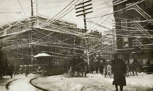 (via Retronaut)
At that time, the nascent power companies each used their own separate AC voltages and transmission lines, leading to a chaotic jumble of wires overhead. Eventually, standard voltages (i.e. 480VAC, 208VAC, etc.) were agreed upon in order to allow for the consolidation of transmission lines. However, these figures are essentially arbitrary numbers that were established simply to allow for greater universality. A 500VAC or 250VAC standard would do the trick just as well…they just didn’t get chosen.
Feel free to post any questions or comments below. We’d love to hear what you think about this!